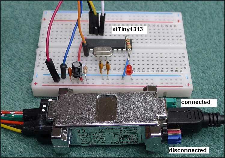
On the picture there is a ATtiny4313 on a breadboard and some parts. The crystal with 2 capacitors is for setting an exact frequency, in our case 8MHz. Maximum is 20MHz. The capacitors 100M and 10n are usefull for filtering supply voltage.
To use an ATtiny4313 or another controller from AVR family we need also a device for programming it. It is a programmer with an interface cable to an USB port of a PC. Here the AVRPROG USB V2 is used, but there are also other programmers which fulfill the same task. Their work is to enable copy of a program from the PC to code (flash) memory of the AVR. The interface is a cable connected to USB port and on the AVR site there is a 6 or in our case 10 pin connector. Pin layout is on the programmer image below under the red arrow.


This programmer has 3 bridge switches (jumpers). Here only the green one is used. The blue and red ones are in position "unconnected", hanging only on one pin. Closing the green bridge brings the 5V voltage from USB connector of PC to the output pins of the programmer. Otherwise another power supply is needed for the ATtiny4313 board.
Drivers needed for the programmer and all other documentation is on the web.
In ASM after the begin label the stacker pointer SP is initialised with the end of data memory RAMEND. It is used by calls and returns from a subroutine, in our case delay. As the ATtiny4313 has only 256 bytes of RAM, only SPL is relevant, SPH could be initialised with 0x00. But it works also as it is.
How to end the program execution in ASM ? Disassembling the GCC version showed as last executed instruction a jump to the program counter PC with the current instruction address. It stops the instructions execution in a way, that it runs execution of a jump instruction jumping to itself.
Timers and/or counters is a feature, which is well designed for solving many tasks. ATtiny4313 and also some other AVRs are sold with preprogrammed fuses for using an internal oscillator. There are 3 bytes of fuses, they keep their values also, if the chip is not powered.
The best way to achieve a stable frequency is to use a crystal, connected between pins PA0 and PA1. This frequency is defaultly "fused" with bits CKSEL0-3 to use an internal 8 MHZ oscillator and with CKDIV8 fuse bit set for dividing the frequency by 8, so using an 8 MHz crystal results in 1 MHz MCU system clock frequency. There is also a possibility to use an external source for the clock frequency.
 By setting the CKDIV8 fuse bit and CLKPR system clock prescale register bits
CLKPCE and CLKPS0-3 the default prescale can be changed to powers of 2 from 1 to 256.
We have to be carefull not to set the system clock under 4 times of the programmers takt.
The best way is to set the takt of the programmer to 9600 baud, which is low enough.
In the GCC examples clock_prescale_set(clock_div_1) included from power.h is used
to set the prescaler to 1 and so let the system clock to be as high as the oscillator frequency, 8 MHz.
In the ASM examples the default system clock prescaler is accepted and therefore worked with MCU system clock 1 MHz.
By setting the CKDIV8 fuse bit and CLKPR system clock prescale register bits
CLKPCE and CLKPS0-3 the default prescale can be changed to powers of 2 from 1 to 256.
We have to be carefull not to set the system clock under 4 times of the programmers takt.
The best way is to set the takt of the programmer to 9600 baud, which is low enough.
In the GCC examples clock_prescale_set(clock_div_1) included from power.h is used
to set the prescaler to 1 and so let the system clock to be as high as the oscillator frequency, 8 MHz.
In the ASM examples the default system clock prescaler is accepted and therefore worked with MCU system clock 1 MHz.
Interrupts are activated and deactivated global by sei and cli and every one also specific, if used. At the beginning of the flash program memory there is reserved one word for each type of interrupt. In this word a rjump instruction provides skip to the interrupt service routine ISR. The place of not occupied interrupt vectors is free for using by program. Program memory is addressed in words. In first example a TIMER1 OVF interrupt is used, in second example the TIMER1 COMPA interrupt is used.

WGM10,WGM11 are bits of the register TCCR1A, WGM12,WGM13 are bits of the register TCCR1B.

CS10-CS12 are bits of the register TCCR1B.

Bits of register TIMSK are for enabling/disabling of specific timer interrupts.


The GCC examples have set the system clock to 8 MHz with prescaler 1 although we could get the needed frequency between 5 Hz and 0.5 Hz without prescaling the MCU clock, simply using different IO-prescaler setting by bits CS10-CS12 of TCCR1B register and another top value for CTC, or counter capacity for OVF interrupts as it was done in ASM programs.
The BASCOM example is slightly modified, 2 timers are used - TIMER0 for blinking freq. and TIMER1 for duration of led blinking. Both BASCOM interrupt events are activated at timer/counter overflow.
The same situation, but using setting an OCR1A compare register value and CTC Clear Timer on Compare match mode.